


-
Lean SL
LEAN SL STEP BESTANDEN

Unit SL 5.m SL 5.0 SL 5.1 SL 5.3 SL5.5 Lifting power Fmax N 300 800 2000 8000 25000 Lifting speed vmax m/s 0.6 0.6 0.6 0.6 0.6 Acceleration amax m/s² 30 30 30 30 30 Torque Mmax Nm 1.8 8 40 240 1200 Pitch diameter Tk mm 12 20 40 60 96 Lifting gear ratio mm/360° 37.6991 62.8318 125.6637 188.4955 301.5929 Efficiency η 0.8 0.8 0.8 0.8 0.8 Temperature resistance t °C +100 -10 to + -100 -10 to + 100 – -10 to +100 +100 Static torque Mtx stat. Nm 0 0 0 0 0 Dynamic torque Mtx dyn. Nm 0 0 0 0 0 Mty stat. Nm 100 200 400 2000 7000 Mty dyn. Nm 9 18 22 150 800 Mtz stat. Nm 250 500 1000 4000 15000 Mtz dyn. Nm 25 50 110 700 4500
Unit SL 5.m SL 5.0 SL 5.1 SL 5.3 SL 5.5 A mm 60 80 110 180 305 B mm 60 80 110 180 305 C mm 47 70 80 130 200 D mm 36 55 60 105 160 E mm 40 50 72 120 210 F mm 44 59 85.5 139.5 231.5 G mm 20 26 30 55 90 Locating flange H mm 19 K6 26 K6 47 K6 72 K6 125 K6 I mm 35 48 72 110 200 J mm 9.5 h7 14 h7 25 h7 42 h7 65 h7 K mm 22 30 46 60 90 L mm 22 32 47 62 92 M mm 14 25 35 50 80 N mm 2.5 2 5 5 5 Ker DIN 6885 P9 O mm 6 H7 10 H7 20 H7 35 H7 55 H7 P mm 4 H7 6 H7 6 H7 6 H7 10 H7 R mm 4 H7 6 H7 6 H7 6 H7 10 H7 S mm M6 M8 M10 M12 M20 5.0 through 6.8 through 8,5 through 10,2 through 17.5 through T mm M5 M6 M8 M10 M12 Lube hole U mm M6 M10 M10 M10 M10 V mm 40 52 60 100 145 W mm 12 15 18 35 60 Gear rack protection X mm M3 M4 M4 M4 M5 Weight PW kg 0.36 1.00 2.35 9.70 44.1 Weight ZA 1 kg 0.39 1.11 2.70 11.55 49.6 Weight ZA2 kg 0.40 1.15 2.87 12.21 51.9 Weight PFN kg 0.37 1.03 2.32 9.91 43.5
Tandheugel


Unit SL 5.0 SL 5.1 SL 5.3 A mm 25 h6 32 h6 60 h6 B mm M10 M12 M20 C mm 30 35 50 Number teeth Z as per customer data Module m 1 2,5 2,5 tooth pitch to mm 3,1416 7,854 7,854 Moment of inertia Ix mm4 12054 24330 352513 Moment of Iinertia Iy mm4 177856 44042 572284 Polar moment of inertia Ip mm4 29910 68372 924797 Weight kg/m 3,5 5,45 19,1 -
Lifgo Gear
LIFGO GEAR STEP BESTANDEN

Unit 5.0 5.1 5.3 5.4 Lifting power Fmax N 2000 3800 15900 25000 Lifting speed Vmax m/s 3 3 3 3 Acceleration amax m/s2 50 50 50 50 Torque Mmax Nm 20 76 477 1000 Pitch diameter pt. mm 20 40 60 80 Lifting gear ratio mm/360° 62.8318 125.6637 188.4955 251.3274 Efficiency η 0.92 0.92 0.92 0.92 Temperature resistance t °C -10 to +80 -10 to +80 -10 to +80 +80 Static torque Mtx stat. Nm 570 760 4400 5500 Dynamic torque Mtx stat. Nm 280 390 2200 2800 Mty stat. Nm 380 650 3300 3300 Mty dyn. Nm 180 330 1600 1600 Mtz stat. Nm 380 650 3300 3300 Mtz dyn. Nm 180 330 1600 1600 Static load rating F stat. N 38400 51200 161400 161400 Dynamic load rating F dyn. N 19100 25900 79600 79600 Unit 5.0 5.1 5.3 5.4 A mm 80 110 180 180 B mm 80 110 180 200 C mm 70 80 130 165 D mm 55 60 105 130 E mm 50 72 120 140 E2 135 F mm 59 85,5 139,5 159,5 G mm 26 30 55 55 G1 mm 7,5 16 21,5 31,5 G2 mm 7 7 13 13 Locating flange H mm 38.5 H7 59 H7 92 H7 117 H7 I mm 48 0 72 0 110 0 135 Key DIN 6885 P9 J mm 14 h7 25 h7 42 h7 55 h7 K mm 30 45 60 80 L mm 32 47 62 82 M mm 25 36 50 70 N mm 2 5 5 5 Key DIN 6885 P9 O mm 10 H7 20 H7 35 H7 50 H7 P mm 6 H7 6 H7 6 H7 6H 7 R mm 6 H7 6 H7 6 H7 6 H7 S mm M8 M10 M12 M12 6.8 through 8.5 through 10.2 through 10.2 through S1 mm 8.5 10.5 12.5 12.5 M8 M10 M12 M12 6.8 through 8.5 through 10.2 through 10.2 through T mm M6 M8 M10 M10 Lube hole U mm M10 x 1 M10 x 1 M10 x 1 M10 x 1 Lube hole U1 mm M6 M6 M6 M6 V mm 58 62 100 120 W1 mm 5.5 8 21.5 21.5 W2 mm 15.5 18.5 30 30 X mm M4 M4 M4 M4 Weight PW kg 2.25 5.10 14.30 25.3 Weight ZA1 kg 2.36 5.45 16.15 26.8 Weight ZA2 kg 2.40 5.62 16.81 26.8 Weight PFN kg 2.28 5.07 14.51 21.2 Tandheugel


Unit SL 5.0 SL 5.1 SL 5.3 A mm 23 27 48 A1 mm 21 25 46 B mm M10 M12 M20 C mm 30 35 50 D mm 26 31,5 48,5 E mm 16 18,5 26,5 Gear rack length L mm L = Z x to Number teeth Z as per customer data Module m 1 2,5 2,5 tooth pitch to mm to = m x Pi Moment of inertia Ix mm4 16411 22961 253179 Moment of Iinertia Iy mm4 24216 35018 297984 Polar moment of inertia Ip mm4 40628 57979 551164 Weight kg/m 3,82 4,84 14,45 Lifgo linear
LIFGO LINEAR STEP BESTANDEN

unit 5.0 5.1 5.3 5.4 A mm 80 110 180 180 B mm 71.5 98.5 161 181 B1 mm 40 55 90 100 C mm 70 80 130 165 D mm 55 60 105 130 E mm 50 72 120 140 E1 mm 15 19 30 30 E2 135 F mm 3.5 5,5 5 5 G mm 26 30 55 55 G1 mm 7,5 16 21,5 31,5 G2 mm 7 7 13 13 locating flange H mm 38.5 H7 59 H7 92 H7 117 H7 I mm 48 72 110 110 Key DIN 6885 P9 J mm 14 h7 25 h7 42 h7 55 h7 K mm 30 45 60 80 L mm 32 47 62 82 M mm 25 36 50 70 N mm 2 5 5 5 Key DIN 6885 P9 O mm 10 H7 20 H7 35 H7 50 H7 P mm 6 H7 6 H7 6 H7 6 H7 R 6 H7 S mm M8 M10 M12 M12 6.8 through 8.5 through 10.2 through 10.2 through T mm M6 M8 M10 M10 Lube hole U mm M10 x 1 M10 x 1 M10 x 1 M10 x 1 Lube hole U1 mm M6 M6 M6 M6 V mm 58 62 100 120 W mm 18 21 43 43 X mm M4 M4 M4 M4 Weight PW kg 2.15 4.85 13.25 20 Weight ZA1 kg 2.26 5.20 15.10 24 Weight ZA2 kg 2.30 5.37 15.76 25.5 Weight PFN kg 2.20 4.82 13.46 19.9 Tandheugel


Unit 5.0 5.1 5.3 A mm 23 27 48 A1 mm 21 25 46 B mm M10 M10 M12 C mm 15 15 20 D mm 26 31,5 48,5 E mm 62,831853 62,831853 109,955743 E1 mm 31,42 31,42 54,98 E2 mm 94,25 94,25 164,93 E3 mm 157,08 157,08 274,89 Hole spacing from front end En mm En = Ze x m x Pi x (n-1/2) Gear rack length L mm L = Z x to Max. number of holes Nmax. each Whole number Nmax. = (Z-Ze/2-2)/Ze+1 Number of teeth Z each as per customer data Number of teeth between two holes Ze each 20 8 14 Module m 1 2,5 2,5 Tooth pitch to mm to = m x Pi Moments of inertia Ix, Iy, Ip kg/m see lifgo gear rack Weight 3,82 4,84 14,45 ELZA
ELZA STEP BESTANDEN

Size ELZA 40 ELDZA 60 ELDZA 60 S ELDZA 80 ELDZA 80 S ELDZA 100 Forces/Torques static dynamic static dynamic static dynamic static dynamic static dynamic static dynamic Fx (N) 900 750 1500 1200 1500 1200 2200 1800 2200 1800 2900 2500 Fy (N) 1200 700 3000 2000 4100 3100 3000 2000 4600 3600 8000 6500 Fz (N) 900 650 1700 1100 2160 1600 1700 1100 3000 1800 3600 2200 Mx (Nm) 25 20 67 43 88 65 90 55 170 140 300 230 My (Nm) 32 18 90 70 190 140 110 80 270 230 400 270 Mz (Nm) 35 25 120 100 230 170 150 120 300 220 750 500 Speed (m/s) max 2 2,5 2,5 3 3 3 Geometrical moments of inertia of aluminium profile Ix mm4 1,32×10⁵ 4,86×10⁵ 4,86×10⁵ 18,99×10⁵ 18,99×10⁵ 44,4×10⁵ Iy mm4 1,34×10⁵ 4,87×10⁵ 4,87×10⁵ 18,97×10⁵ 18,97×10⁵ 44,8×10⁵ E-Modulus N/mm² 70000 70000 70000 70000 70000 70000 Size Basic length L A B C D – 0,05 E F G H I J K KK for M MM for N NN for OO for P Q T V Basic weight ELZA 40 150 100 21,5 58 37 18 32 60 56 – 35 6,5 – 47 – 100 M6 M6 12 122 M6 – 2,0 kg ELDZA 60 205 144 28,0 82 47 30 42 75 63 – 49 8,5 M6 69 – 130 M8 M8 16 168 M6 – 4,7 kg ELDZA 60S 230 170 34,5 82 47 30 42 92 63 – 53 8,5 M6 69 – 150 M8 M8 16 194 M6 10 7,2 kg ELDZA 80 240 170 39,0 102 68 40 60 105 100 30,5 70 8,5 – 88 M6 170 M10 M10 20 194 M8 10,5 11,9 kg ELDZA 80S 260 190 39,0 102 68 40 60 105 100 30 71 8,5 – 88 M6 170 M10 M8 20 214 M8 12,5 12,9 kg ELDZA 100 360 230 55,3 130 90 50 80 155 120 29 89 10,5 – 112 M10 240 M10 M10 30 300 M10 24,0 kg Size Version 1 Version 2 Version 3 Q L Q L Q L 40 227 255 138 166 243 271 60 303 340 184 221 319 356 605 349 386 214 251 369 406 80 369 415 210 256 385 431 80S 389 435 234 280 409 455 100 505 565 316 376 521 581 Size Shaft Ø h6 x length Key Pinion mm/rev. Modul 40 14 x 30 5x5x28 188,5 1,5 60 18 x 30 6x6x28 251,3 2 60 S 18 x 30 6x6x28 314,2 2 80 (S) 28 x 40 8x7x35 358,0 3 100 28 x 40 8x7x35 508,9 3 ELZA 40 0,35 kg / 100 mm ELDZA 60 Polyamide rack 0,56 kg / 100 mm ELDZA 60 Steel rack 0,78 kg / 100 mm ELDZA 80 Polyamide rack 0,95 kg / 100 mm ELDZA 80 Steel rack 1,48 kg / 100 mm ELDZA 100 Polyamide rack 1,48 kg / 100 mm ELDZA 100 Steel rack 1,99 kg / 100 mm ELZQ
ELZQ STEP BESTANDEN

Size ELZQ 60 h6 ELZQ 60 h7 ELZQ 80 h6 ELZQ 80 h7 ELZQ 80S h6 ELZQ 80S h7 Forces/Torques static dynamic static dynamic static dynamic static dynamic static dynamic static dynamic Fx (N) 1800 1400 940 780 1800 1400 940 780 1800 1400 940 780 Fy (N) 3000 2000 3000 2000 3000 2000 3000 2000 4600 3600 4600 3600 Fz (N) 1700 1100 1700 1100 1700 1100 1700 1100 3000 1800 3000 1800 Mx (Nm) 67 43 67 43 90 55 90 55 170 140 170 140 My (Nm) 90 70 90 70 110 80 110 80 270 230 270 230 Mz (Nm) 120 100 120 100 150 120 150 120 300 220 300 220 Speed (m/s) max 4 4 4 4 4 4 Geometricalmoments of inertia of aluminium profile Ix mm4 6,79×10⁵ 6,79×10⁵ 18,99×10⁵ 18,99×10⁵ 18,99×10⁵ 18,99×10⁵ Iy mm4 6,97×10⁵ 6,97×10⁵ 18,97×10⁵ 18,97×10⁵ 18,97×10⁵ 18,97×10⁵ E-Modulus N/mm² 70000 70000 70000 70000 70000 70000 Size Basic length L A B C D Ø ±0,05 E G H J K M N NN for OO for P Q T Basic weight Weight per 100 mm ELZQ 60 230 144 25,5 82 62 30 71,5 42 49 8,5 69 19 M 8 M 8 16 194 M 10 5,0 kg 0,68 kg ELZQ 80 260 170 25,5 102 80 40 60,5 31 70 8,5 88 25 M 10 M 10 20 214 M 10 11,0 kg 1,19 kg ELZQ 80S 280 190 25,5 102 80 40 60,5 31 71 8,5 88 13 M 10 M 8 20 234 M 10 12,0 Kg 1,19 kg Size Version 1 Version 2 Version 3 Q L Q L Q L 60 338 374 210 246 354 390 80 384 430 230 276 400 446 80S 404 450 254 300 420 466 Size Shaft ø h6 x length Key Pinion mm/rev. Modul 60 20 x 29,5 6x6x25 100 1,6 80 (S) 20 x 29,5 6x6x25 100 1,6 Nieuw product
Tandheugelsystemen zijn over het algemeen zeer geschikt voor hoog dynamische bewegingen. De stijfheid in de aandrijving zorgen voor een hoge positioneernauwkeurigheid.
De LEAN SL serie van LEANTECHNIK AG is gebaseerd op ronde tandheugels (niet gehard) gecombineerd met glijlagers.
De LIFGO-serie van LEANTECHNIK AG is gebaseerd op rollenomloopgeleiding, waarbij de rail tevens de tandheugels omvat met geharde en geslepen vertanding.
Zowel de LEAN SL-serie als de LIFGO-serie zijn “double” uit te voeren, waarbij twee tandheugels door 1 rondsel wordt aangedreven. Uitermate geschikt voor link-rechts bewegingen in o.a. breedte verstellingen, grijpers, etc.
Voor lange slagen is er de LIFGO LINEAR-serie. Hierbij is de rail voorzien van draadgaten waarmee de rail aan uw frame gemonteerd wordt. De slede wordt aangedreven en is voorzien van montage gaten.
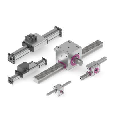
De ELZA-serie en ELZQ-serie van BAHR MODULTECHNIK is een op aluminium extrusie gebaseerd tandheugelsysteem. Hoofdzakelijk zeer geschikt als verticale as voor handlingsystemen. Bij de ELZA-serie is er keuze uit verschillende materialen tandheugels en rondsels: C45, RVS of PA6. De herhaalnauwkeurigheid is±0,2 mm. De ELZQ-serie is alleen leverbaar met tandheugels van Cf53 met h6/h7 vertandingsnauwkeurigheid (gehard en geslepen). De herhaalnauwkeurigheid is ±0,1 mm.


